Asset Tracker Guide & Signal Troubleshooting
This guide covers setup, LED diagnostic indicators, mounting best practices, and location behavior for the Asset Tracker.
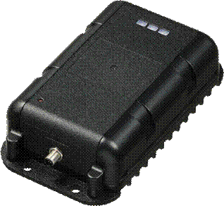 1. Device Setup & Power Controls
Hardware Components: Package includes the ST4932 tracker, 8 assembly screws, Micro-USB data cable, and charging cables (12V-to-5V & USB).
Inserting the SIM Card:
Disconnect all power sources (internal battery, external DC, and USB).
Remove the 4 inner assembly screws using a PH#0 driver (do not use outer screw holes).
- Disconnect the 4-pin battery connector.
- Insert the Nano-SIM (4FF) into the slot following the notch orientation on the PCB.
Power & Reassembly:
Reconnect the 4-pin battery cable (red wire oriented properly). A small red LED on the PCB will illuminate to confirm power.
- Seat the top casing onto the base gasket and tighten all 8 assembly screws.
Power On / Off & Status Checks: Use a paperclip or pin to press the internal red button:
Power On: Press & hold ~5s until red LED turns solid. Release; blue/red LEDs will blink.
Power Off: Press & hold ~5s until red LED turns solid. Release; red LED will blink 15 times.
Quick Status Check: Press ~1s. If off, red LED blinks. If on, all active status LEDs blink.
2. Diagnostic LED Status Guide
Note: LEDs automatically turn off when the device enters Sleep or Deep Sleep power-saving modes.
| LED Color | Blinks | Status / Meaning |
| Red (GNSS / GPS) | 1 2 4 | Location Fixed Location Not Fixed Antenna Error |
| Blue (Cellular Network) | 1 2 3 4 5 6 7 8 | Carrier & Server Connected Carrier Connected; Server Error GPRS/HSPA Error Carrier Not Connected SIM PIN Locked Cannot Attach to Network No SIM Installed SIM PUK Locked |
| Purple (Battery SOC) | 1 2 3 4 Off | 25% Charged 50% Charged 75% Charged < 100% Charged Fully Charged |
3. Mounting & Placement Best Practices
Securing the Unit:
Best: Use mounting screws through the 4 dedicated frame mounting holes (3/16 x 4): most secure
Acceptable: Use heavy-duty zip ties 5/16 in wide to use slots through the body slots.
Avoid: Do not leave the unit loose or use adhesive backing.
Signal Clearance:
Optimal: Mount facing face-up toward the open sky.
Acceptable: Mount under glass or non-metallic plastic surfaces.
Avoid: Do not fully enclose inside metal compartments, as this blocks GPS and cellular signals.
4. Understanding Location Behaviors & Signal Messages
"Establishing Signal" Status:
Meaning: The tracker attempted a scheduled report but could not obtain a clear GPS fix (often due to being parked inside a metal building or dense enclosure).
Resolution: Move the asset outdoors with an unobstructed view of the sky. The status will resolve on the next scheduled ping.
Imprecise Map Location (Cell Trilateration):
Meaning: When GPS signals are blocked, the tracker enters fallback mode, estimating position using nearby cell towers.
Behavior: The map shows an approximate area (typically within a 1/2-mile radius) instead of exact coordinates.
Resolution: Return the asset to an open-air environment to re-establish exact GPS positioning.
Delayed Location Updates (Low Cellular Coverage):
Meaning: In weak coverage areas, the tracker stores location logs in local memory and uploads them once reception recovers.
Behavior: Battery and diagnostic data may update on the portal before queued location points catch up.
Resolution: Verify cell coverage in the area; stored tracking points will automatically backfill once network connectivity restores.
Support Contact
For hardware issues or persistent connection failures, reach out to Fleetr Support:
Email:
support@fleetr.appPhone: 1-415-651-7575